
The document describes the features and characteristics of the DS1855 series products, including different models of linear potentiometers, EEPROM memory, 2-wire interface, etc.
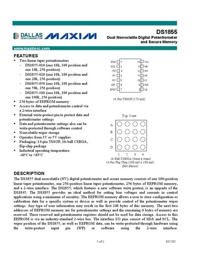
The DS1855 is a dual nonvolatile digital potentiometer that includes two linear‑taper potentiometers (one 100‑position and one 256‑position) and 256 bytes of EEPROM memory. It is accessed via a standard 2‑wire (I²C‑compatible) serial interface and supports both hardware and software write‑protect features.
Three package options are offered (14‑pin TSSOP, 16‑ball CSBGA, and 14‑pin flip‑chip) and the device operates from 2.7 V to 5.5 V with an industrial temperature range of –40 °C to +85 °C. Up to eight devices can share a single 2‑wire bus using address pins AO‑A2.
| Supply voltage range | 2.7 V to 5.5 V |
|---|---|
| Operating temperature | -40 °C to +85 °C |
| Package options | 14‑Pin TSSOP, 16‑Ball CSBGA, 14‑Pin Flip Chip |
| Potentiometer positions | Pot0: 100 positions, Pot1: 256 positions |
| EEPROM memory size | 256 bytes |
| Maximum devices on bus | 8 |
Up to eight DS1855 devices can share a single 2‑wire bus using unique address pins.
Both SDA and SCL are open‑drain lines that are normally pulled high with an external resistor.
The DS1855 is offered in 14‑pin TSSOP, 16‑ball CSBGA (4 mm × 4 mm), and 14‑pin flip‑chip packages.