
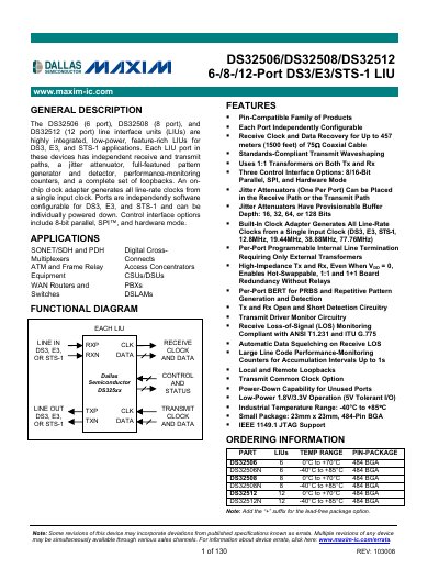
The DS32506, DS32508, and DS32512 are 6-, 8-, and 12-port line interface units for DS3, E3, and STS-1 applications. Each port has independent receive and transmit paths, a jitter attenuator, a pattern generator and detector, performance-monitoring counters, and loopbacks.
The datasheet covers standards compliance, block and application diagrams, pin descriptions, functional operation, register maps, JTAG information, electrical characteristics, pin assignments, and package and thermal information. It also lists ordering options, including industrial-temperature versions.
| Port count | 6, 8, or 12 ports |
|---|---|
| Supported applications | DS3, E3, and STS-1 |
| Control interface options | 8/16-bit parallel, SPI, and hardware mode |
| Jitter attenuator buffer depth | 16, 32, 64, or 128 bits |
| Input clock frequencies | 12.8 MHz, 19.44 MHz, 38.88 MHz, 77.76 MHz |
| Industrial temperature range | -40°C to +85°C |
| Package | 23 mm x 23 mm, 484-pin BGA |
| Power | 1.8 V/3.3 V operation, 5 V tolerant I/O |
The devices support DS3, E3, and STS-1 applications.
The devices offer 8/16-bit parallel, SPI, and hardware mode.
Each jitter attenuator can be provisioned for 16, 32, 64, or 128 bits.
The devices are offered in a 23 mm x 23 mm, 484-pin BGA.