
XC9103/XC9104/XC9105 series are PWM, PWM/PFM auto switching /manual switching controlled universal step-up DC/DC converter controllers. Output will be stable no matter which load capacitors are used but should a low ESR capacitor be used, RSENSE of about 0.1Ω will be required and phase compensation will be achieved. This allows the use of ceramic capacitors and enables to obtain lower output ripple and small PCB design. Tantalum and electrolytic capacitors can also be used, in which case, RSENSE becomes unnecessary. With 0.9V internal voltage reference and by using externally connected two resistors, output voltage can be set freely within a range of 1.5V to 30V. The series is available in 300 kHz and 180 kHz frequencies, the size of the external components can be reduced. 100 kHz and 500 kHz are also available in custom options. The XC9103 offers PWM operation. The XC9104 offers PWM/PFM automatic switching operation. The PWM operation is shifted to the PFM operation automatically at light load so that it maintains high efficiency over a wide range of load currents. The XC9105 offers both PWM and PWM/PFM auto switching operations and it can be selected by external signal. A current limiter circuit is built-in to the IC (except with the 500 kHz version) and monitors the ripple voltage on the FB pin. Operation is shut down when the ripple voltage is more than 250mV.
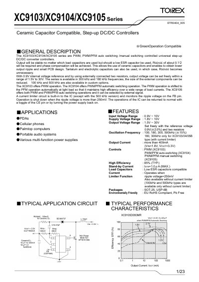
The XC9103/XC9104/XC9105 series are universal step‑up DC/DC controller ICs offering PWM, PWM/PFM auto‑switching and manual switching modes. They support a wide input range, selectable output voltage from 1.5 V to 30 V and high efficiency up to 85 %.
The document provides detailed electrical characteristics, pin configurations, typical application circuits, packaging information and marking rules, helping designers integrate the devices into portable audio, PDA, cellular phone and other multi‑function power supply applications.
| Input Voltage Range | 0.9 V ~ 10 V |
|---|---|
| Supply Voltage Range | 1.8 V ~ 10 V |
| Output Voltage Range | 1.5 V ~ 30 V |
| Maximum Output Current | ≥ 400 mA (VIN=1.8 V, VOUT=3.3 V) |
| Oscillation Frequency Options | 100 kHz, 180 kHz, 300 kHz, 500 kHz (±15 %) |
| Stand‑by Current | 1.0 µA (max) |
| Over‑current Sense Voltage | 250 mV |
| Package Types | SOT‑25, USP‑6B |
The devices can be set to output voltages from 1.5 V up to 30 V.
They are offered at 100 kHz, 180 kHz, 300 kHz and 500 kHz, with custom options possible.
A built‑in current‑limit circuit monitors the ripple voltage on the FB pin and shuts down the IC when the ripple exceeds 250 mV.