
XC9223/XC9224 series are synchronous step-down DC/DC converters with a 0.21Ω (TYP.) P-channel driver transistor and a synchronous 0.23Ω (TYP.) N-channel switching transistor built-in.
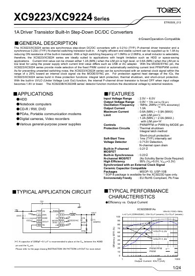
The XC9223/XC9224 series are synchronous step‑down DC/DC converters that integrate a P‑channel driver transistor and an N‑channel switching transistor. They provide up to 1 A output current with high efficiency (up to 95 % at 5 V → 3.3 V) and support PWM or PWM/PFM control modes.
The devices operate from 2.5 V to 6.0 V input, offer selectable output voltage, and include protection features such as integral latch, thermal shutdown, and short‑circuit protection. They are supplied in MSOP‑10, USP‑10B and SOP‑8 packages and are RoHS‑compliant.
| Input Voltage Range | 2.5 V – 6.0 V |
|---|---|
| Output Voltage Range | 0.9 V – VIN |
| Oscillation Frequency | 1 MHz, 2 MHz (±15 % accuracy) |
| Current Limit (LIM pin high) | 1.2 A – 2.0 A |
| Built‑in P‑channel MOSFET Rds(on) | 0.21 Ω (typ.) |
| Built‑in N‑channel MOSFET Rds(on) | 0.23 Ω (typ.) |
| Efficiency (5 V → 3.3 V, 200 mA) | 95 % |
| Operating Temperature Range | -40 °C to +85 °C |
| Package Types | MSOP‑10, USP‑10B, SOP‑8 (XC9223D only) |
The converters operate from 2.5 V to 6.0 V input.
They include integral latch protection, thermal shutdown, and short‑circuit protection.
By using external resistors RFB1 and RFB2 to form a voltage divider; the output voltage follows VOUT = 0.8 × (RFB1 + RFB2)/RFB2.
The devices are offered in MSOP‑10, USP‑10B, and SOP‑8 (XC9223D only) packages.