
The TSW140x high-speed data capture/pattern generator card is a next generation of pattern generator and data capture card used to evaluate performances of a wide range of Texas Instruments (TI) high-speed analog-to-digital converters (ADC) and digital-to-analog converters (DAC). For an ADC, capturing the sampled data over an LVDS interface when using a high-quality, low-jitter clock, and a high-quality input frequency, the TSW1400 can be used to demonstrate data sheet performance specifications. Together with the accompanying Labview based Graphic User Interface (GUI), it is a complete system that captures and evaluates data samples from ADC EVM’s and generates and sends desired test patterns to DAC EVM’s The TSW1405 is a low cost data capture card with limited capabilities as compared with the TSW1400. The TSW1405 supports pattern capture for most LVDS format TI ADC EVMs, but with a capture buffer limitation of 64K samples. The TSW1405 draws its power from the USB connection to the PC for easy setup and operation. The same TSW1400 Graphical User Interface supports the TSW1405 as well, making for a consistent feel across the different platforms. The TSW1406 is a low cost pattern generator card with limited capabilities as compared with the TSW1400. The TSW1406 supports pattern generation for most LVDS format TI DAC EVMs, but with a pattern limitation of 64K samples. The TSW1406 draws its power from the USB connection to the PC for easy setup and operation.
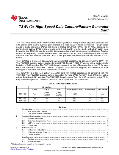
This guide describes the TSW1400 evaluation module, a high‑speed data capture and pattern‑generator card used to evaluate Texas Instruments ADC and DAC evaluation modules. It covers the hardware architecture, power supplies, connectors, and the accompanying LabVIEW‑based GUI for data acquisition and test‑pattern generation.
The document details hardware configuration (power connections, LED indicators, jumpers, and connectors), software installation, USB driver setup, and step‑by‑step operation of both ADC data capture and DAC pattern generation functions. It also includes troubleshooting notes for firmware mismatches and board connection issues.
| Output voltage 1 | 3.3 V @ 3 A (J10) |
|---|---|
| Output voltage 2 | 1.8 V @ 6 A (J8) |
| Pattern buffer limit (TSW1406) | 64 K samples |
It provides 3.3 V at up to 3 A on connector J10 and 1.8 V at up to 6 A on connector J8.
The TSW1406 supports pattern generation with a maximum of 64 K samples.