
The LTC1264 is a high speed, quad universal filter building block from LTC company. It has a center frequency up to 250kHz and a 0.3 inch wide package. The device also features four identical filters and a power supply voltage range of ±2.37V to ±8V.
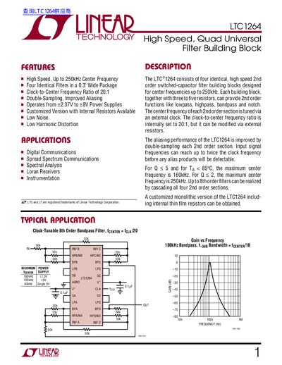
This document describes the LTC1264, a high‑speed, quad‑universal switched‑capacitor filter building block. It outlines its features, applications, and the four identical 2nd‑order filter sections that can be configured as low‑pass, high‑pass, band‑pass, or notch filters.
Key sections include absolute maximum ratings, electrical characteristics, pin functions, several modes of operation (Modes 1, 1b, 2, 3, 3a, 2n), typical performance graphs, package dimensions, and a typical 8th‑order band‑pass application circuit.
| Operating Supply Range | +2.375 V to +8 V |
|---|---|
| Clock‑to‑Center Frequency Ratio | 20:1 |
| Maximum Clock Frequency | 6 MHz (V+ = +7.5 V, 25 °C) |
| Output Short‑Circuit Current | 3 mA |
| DC Open‑Loop Gain | 80 dB |
| GBW Product | 7 MHz |
| Slew Rate | 10 V/µs |
| Operating Temperature Range | -40 °C to 85 °C |
The internal clock‑to‑center frequency ratio is set to 20:1, but it can be modified with external resistors.
The device operates from a supply voltage of +2.375 V up to +8 V.
At a +7.5 V supply and 25 °C, the maximum clock frequency is 6 MHz.
Pins 7 and 19 (V+ and V‑) are the power‑supply pins and should each be bypassed with a 0.1 pF capacitor to analog ground.