
The HMC305LP4 and HMC305LP4E are broadband 5-bit positive control GaAs IC digital attenuators with CMOS compatible serial-to-parallel drivers packaged in leadless QFN 4x4 mm SMT packages. Covering 0.7 to 3.8 GHz, the insertion loss is typically less than 1.5 to 2 dB. The attenuator bit values are 0.5 (LSB), 1, 2, 4, and 8 dB for a total attenuation of 15.5 dB. Attenuation accuracy is excellent at ±0.25 dB typical with an IIP3 of up to +52 dBm. Five bit serial control words are used to select each attenuation state. A single Vcc bias of +3V to +5V applied through an external 5k Ohm resistor is required. The HMC305LP4 / HMC305LP4E is ideal for: • Cellular/3G Infrastructure • Fixed Wireless, WiMax & WiBro • Test Instrumentation
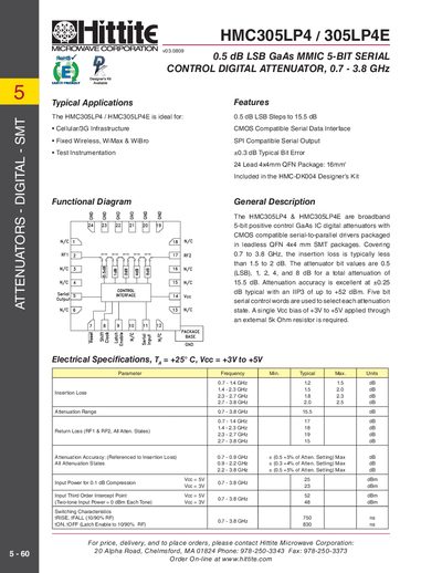
The HMC305LP4 and HMC305LP4E are broadband 5‑bit GaAs MMIC digital attenuators with CMOS‑compatible serial‑to‑parallel drivers. They offer 0.5 dB LSB steps from 0.7 GHz to 3.8 GHz, making them suitable for cellular, Wi‑Max, test instrumentation, and other RF applications.
The devices are supplied in a 24‑lead 4 × 4 mm QFN package, require a single VCC bias of +3 V to +5 V through a 5 kΩ resistor, and include detailed pin assignments, absolute maximum ratings, and recommended PCB layout guidelines. Electrical specifications such as insertion loss, return loss, and attenuation accuracy are listed for multiple frequency bands.
| Frequency Range | 0.7 – 3.8 GHz |
|---|---|
| Attenuation Step Size | 0.5 dB LSB |
| Insertion Loss (0.7‑1.4 GHz) | 1.2 dB (typical) |
| Attenuation Range | 0 – 15.5 dB |
| Return Loss (2.7‑3.8 GHz) | 15 dB |
| Attenuation Accuracy | +0.5 dB +5 % of setting (0.7‑0.9 GHz) |
| Input Power for 0.1 dB Compression | +23 dBm |
| Third‑Order Intercept Point (IIP3) | +52 dBm |
| tRise / tFall (10/90% RF) | 750 ns |
It operates from 0.7 GHz to 3.8 GHz.
The attenuator provides 0.5 dB LSB steps.
A single VCC bias of +3 V to +5 V applied through a 5 kΩ resistor is required.
It can handle up to +26 dBm of RF input power.