
Guidelines for proper MSL handling, reflow soldering, and post‑process procedures for the Vicor SM‑ChiP module.
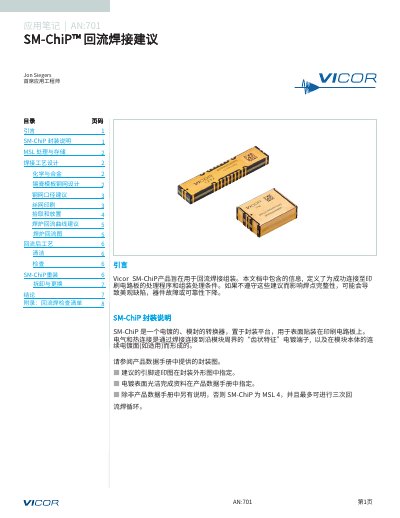
This document provides detailed recommendations for assembling the Vicor SM‑ChiP™ module using reflow soldering. It covers handling, storage, solder paste stencil design, pick‑and‑place, reflow oven profile, cleaning, inspection, and rework procedures.
Key sections include MSL handling and storage, chemistry and alloy selection, stencil aperture guidelines, recommended reflow curve parameters, post‑process cleaning, inspection criteria, and step‑by‑step disassembly and replacement instructions. This manual is written in Chinese.
| Moisture Sensitivity Level | MSL 4 (max three reflow cycles) |
|---|---|
| Recommended Reflow Peak Temperature | 235 – 245 °C (ideal 240 °C) |
| Time Above Liquidus (tL) | 30 – 90 s (ideal 60 s) |
| Stencil Material | Fine‑grain stainless steel |
| Stencil Thickness | 4 – 7 mils |
| Pick‑and‑Place Z‑Axis Pressure | 150 – 500 g |
| Cleaning Requirement | Remove flux residues; water wash compatible |
| Inspection Standard | IPC‑A‑610 |
The SM‑ChiP module is rated MSL 4 and may be reflowed up to three times.
The recommended peak temperature range is 235 – 245 °C, with an ideal target of 240 °C.
The stencil thickness should be between 4 and 7 mils.
All flux residues should be removed from the SM‑ChiP package and surrounding PCB, using a water‑wash compatible process.