
The PerkinElmer A2TPMI sensor module is an integrated thermopile sensor with signal‑processing, temperature compensation and programmable output options.
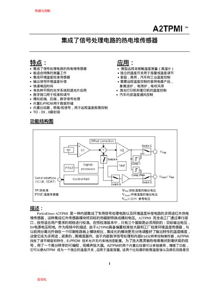
The A2TPMI combines a thermopile detector with on‑chip signal processing and an environmental temperature sensor, providing both target and ambient temperature outputs. It supports analog voltage, comparator mode and serial configuration via a two‑wire SDAT/SCLK interface.
The module is supplied in a TO‑39 6‑pin package, offers programmable gain, bias and comparator thresholds, and includes an on‑board EzPROM for user‑defined settings. Electrical specifications cover a 5 V supply, wide input voltage range, and built‑in reference voltage of 1.225 V. This manual is written in Chinese.
| Supply voltage (VDD) | 4.5 V – 5.5 V |
|---|---|
| Input voltage range | -0.3 V to +6.5 V |
| Operating temperature range | -25 °C to 100 °C |
| Reference voltage (VRef) | 1.225 V (typical) |
| Package | TO‑39, 6 pins |
| Low‑level input voltage (ViL) | 0.3 VDD |
| High‑level input voltage (ViH) | 0.7 VDD |
The typical reference voltage is 1.225 V.
It is housed in a TO‑39 package with six pins.
The sensor operates from –25 °C up to 100 °C.
Output mode (analog or comparator) is selected via an internal analog switch programmed through the two‑wire SDAT/SCLK serial interface.