
Datasheet for the MC100EP140 3.3V ECL Phase-Frequency Detector, detailing pinout, logic, electrical specs, and operating conditions.
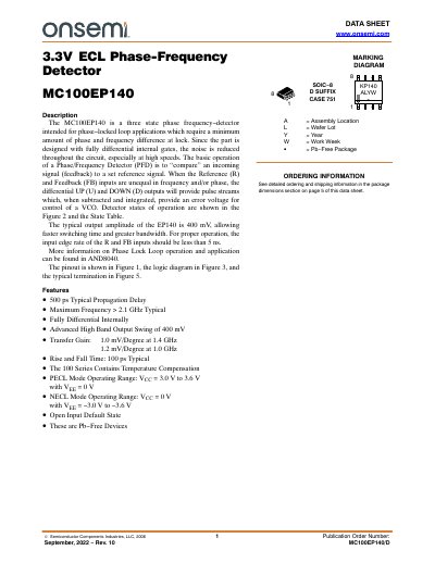
This datasheet describes the MC100EP140, a 3.3V ECL Phase-Frequency Detector designed for phase-locked loop applications. It features fully differential internal gates to reduce noise, with a typical output amplitude of 400 mV and propagation delay of 500 ps. The device supports frequencies up to 2.1 GHz and operates in both PECL and NECL modes. Pin configuration, logic diagrams, and electrical characteristics are provided for design and integration.
| Propagation Delay | 500 ps Typical |
|---|---|
| Maximum Frequency | > 2.1 GHz Typical |
| Output Swing | 400 mV |
| Transfer Gain | 1.0 mV/Degree at 1.4 GHz |
| Operating Temperature | −40 to +85 °C |
| Package | SOIC−8 |
Maximum Frequency > 2.1 GHz Typical.
Advanced High Band Output Swing of 400 mV.
PECL: VCC = 3.0 V to 3.6 V with VEE = 0 V; NECL: VCC = 0 V with VEE = −3.0 V to −3.6 V.
500 ps Typical Propagation Delay.