
User manual for ON Semiconductor's 60W USB-PD evaluation board with active clamp flyback topology.
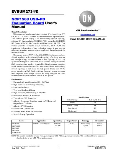
This document provides detailed information on the NCP1568 USB-PD evaluation board, including circuit schematics, PCB layout, BOM, and transformer specifications. It describes the board's active clamp flyback topology using ON Semiconductor components like NCP1568, NCP51530, NCP4305, and FDMS86202. The board supports 5V to 20V output with 3A current and universal AC input (90–265V). Efficiency, transient response, ripple, and thermal data are also included.
The manual includes figures for top and bottom views of the main board and daughter board, magnetic design details, and efficiency curves for each output voltage. It is intended for evaluation purposes only and should not be used to charge USB-PD devices.
| Output Voltage | 5 V, 9 V, 12 V, 15 V, 20 V |
|---|---|
| Nominal Current | 3 A |
| Max Current | 3 A |
| Topology | Active Clamp Flyback |
The board provides 5 V, 9 V, 12 V, 15 V, and 20 V output voltages.
The maximum current is 3 A.
It uses an active clamp flyback topology.