
MoTeC SLM #18120 datasheet: an eight-LED multicolour shift light module wired on the CAN bus and configured from a MoTeC ECU or dash logger.
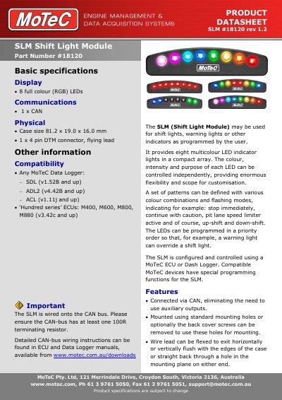
This is the MoTeC product datasheet (rev 1.2) for the SLM Shift Light Module, part number #18120. The module provides eight full colour (RGB) LEDs in a compact array; the colour, intensity and purpose of each LED can be controlled independently, and patterns can be given a priority order so a warning light can override a shift light. It is used for shift lights, warning lights and other indicators, and connects to the CAN bus with a single CAN connection, so auxiliary outputs are not needed.
The SLM has no stand-alone software: it is configured and controlled through the SLM function in the Manager software of the controlling MoTeC device, such as ADL2 Dash Manager or MoTeC ECU Manager. The datasheet lists compatible MoTeC data loggers and 'Hundred series' ECUs, notes that the CAN bus needs at least one 100R terminating resistor, and gives the 4 pin DTM connector pinout, case dimensions and mounting options.
| Display | 8 full colour (RGB) LEDs |
|---|---|
| Communications | 1 x CAN |
| Case size | 81.2 x 19.0 x 16.0 mm |
| Physical | 1 x 4 pin DTM connector, flying lead |
| Connector | DTM 4 pin male |
| Mating connector | DTM 4 pin #68054 |
| Pin 1 | Black, Ground (Battery —) |
| Pin 2 | Green, CAN Low |
| Pin 3 | White, CAN High |
| Pin 4 | Red, + 12 V (Battery +) |
| CAN bus termination | At least one 100R terminating resistor required |
It has eight full colour (RGB) LEDs in a compact array, and the colour, intensity and purpose of each LED can be controlled independently.
The SLM is wired onto the CAN bus and is configured using the SLM function in the Manager software of the controlling ECU or dash logger; it has no stand-alone software package.
Pin 1 is black ground (battery —), pin 2 green CAN Low, pin 3 white CAN High and pin 4 red + 12 V (battery +).
Any MoTeC data logger (SDL v1.52B and up, ADL2 v4.42B and up, ACL v1.11j and up) and the 'Hundred series' ECUs M400, M600, M800 and M880 (v3.42c and up).