
The Mitsumi PST575 datasheet details features, specifications, pin assignments, and application circuits for this ultra‑low‑current system reset IC.
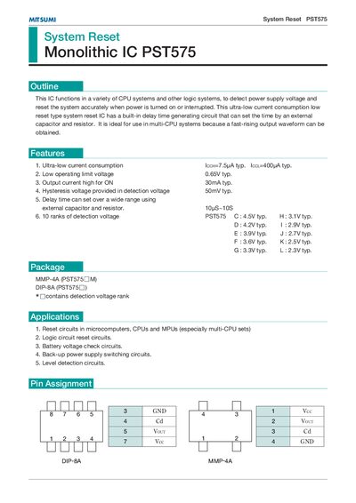
The Mitsumi PST575 is a monolithic system‑reset IC designed for CPU and logic circuits. It provides ultra‑low standby current, a low operating voltage threshold, and an adjustable delay using external components.
The datasheet lists electrical characteristics such as a typical supply current of 7.5 µA, a 30 mA output drive capability, and a 10 µs to 10 s delay range. Application examples include multi‑CPU reset circuits, battery‑voltage monitoring, and backup power switching.
| Supply current (ICCH) typ. | 7.5 µA |
|---|---|
| Low operating limit voltage typ. | 0.65 V |
| Output current high (ON) typ. | 30 mA |
| Hysteresis voltage typ. | 50 mV |
| Delay time range | 10 µs – 10 s |
The typical supply current (ICCH) is 7.5 µA.
The IC can source up to 30 mA typical.
The low operating limit voltage is typically 0.65 V.
The delay time is adjustable over 10 µs to 10 s using an external capacitor and resistor.