
The FB-A safety barrier manual explains features, technical specs, installation, wiring and safety precautions.
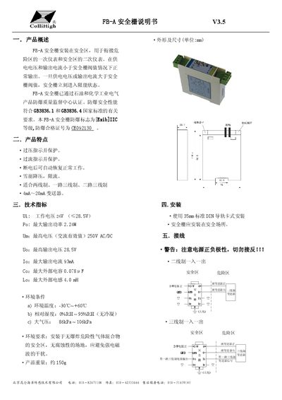
The FB‑A safety barrier is installed in the safety zone to link primary instruments in hazardous areas with secondary instruments in safe zones. It provides over‑voltage and over‑current protection, automatically restores after power loss, and includes avalanche voltage reduction and current limiting. The device complies with GB3836.1 and GB3836.4 explosion‑proof standards (Ex ib IIC) and carries certification CE092130.
The manual details dimensions, wiring for two‑wire and three‑wire configurations, power requirements (24 V supply, ≤28.5 V), and environmental limits (‑30 °C to +60 °C, 0‑95 % RH, 86‑106 kPa). Installation notes stress correct polarity, grounding of the earth symbol, and separation of intrinsically safe and non‑safe circuits. This manual is written in Chinese.
| Working voltage | 24 V (≤28.5 V) |
|---|---|
| Maximum output power | 2.24 W |
| Maximum output voltage | 28.5 V |
| Maximum output current | 93 mA |
| Maximum external capacitance (Co) | 0.078 µF |
| Maximum external inductance (Lo) | 4.0 mH |
| Operating temperature range | -30 °C ~ +60 °C |
| Relative humidity range | 0 % RH ~ 95 % RH (no condensation) |
| Atmospheric pressure range | 86 kPa ~ 106 kPa |
The device operates on a 24 V supply, with a maximum of 28.5 V.
The maximum output current is 93 mA.