
Intersil application note AN1846 for the ISL95813EV1Z evaluation board, covering setup, startup, transient generator use, schematics, layer plots, and BOM.
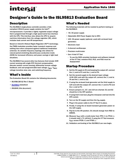
Application Note 1846 describes the Intersil ISL95813EV1Z evaluation board and the ISL95813 single-phase controller, which provides a VR12.6 power supply solution for Intel microprocessors. The document lists kit contents and required test equipment, then gives the startup procedure for the board, including supply connections, jumper and switch settings, and output voltage measurement.
It also explains the on-board transient generator, presents evaluation board schematics and layer plots, and includes the bill of materials. The startup procedure states that VOUT should read 1.7V ±8.5mV, and the on-board transient generator uses resistors R3 and R4 to control the load step and load release slopes.
| Controller | ISL95813 single-phase controller |
|---|---|
| Output voltage | 1.7V ±8.5mV |
| Input voltage range | 4.6V to 19V |
| 5V supply requirement | 5V, 3A power supply |
| Current sensing | DCR current sensing with single NTC thermal compensation |
| Board revision | Rev C |
It is a single-phase controller that provides a fully compliant VR12.6 power supply solution for Intel microprocessors.
The kit contains the ISL95813EV1Z Rev C board, the ISL95813 datasheet, and AN1846.
The second supply can be set to a desired input voltage from 4.6V to 19V.
After startup, VOUT should read 1.7V ±8.5mV when measured from TP9 (+) to TP10 (-).