
The ICP DAS GW-7228 manual explains hardware, software setup, and troubleshooting for J1939 and Modbus RTU communication.
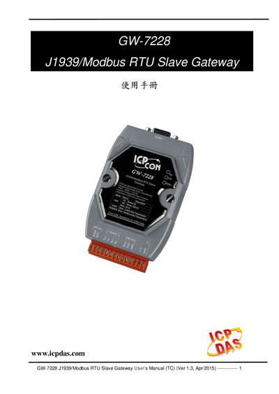
The GW-7228 provides a gateway solution that converts data between J1939 and Modbus RTU networks. It supports PDU1, PDU2, broadcast and targeted J1939 messages, and operates as a Modbus RTU slave. The device includes LED indicators for power, J1939 and Modbus status, a built‑in watchdog, and selectable 120 Ω termination resistors.
The manual covers hardware wiring, CAN and serial port pin assignments, configuration of communication parameters via the GW‑7228 Utility, and detailed troubleshooting steps such as CAN bus failure indicators and factory reset procedures.
| UART connector type | 14‑pin screw terminal |
|---|---|
| COM1 interfaces | RS‑232, RS‑422, RS‑485 |
| Supported baud rates | 2400‑115200 bps |
| CAN connector type | 9‑pin D‑sub |
| CAN baud rate | 250 kbit/s |
| Isolation voltage | 3000 VDC protection, 2500 Vrms isolation |
| Terminal resistor | 120 Ω selectable |
| Dimensions (H×W×D) | 117 mm × 72 mm × 35 mm |
| Operating temperature | -25 °C to 75 °C |
| Storage temperature | -40 °C to 80 °C |
| Humidity range | 5 % to 95 % non‑condensing |
| LED indicators | PWR, J1939, MODBUS status LEDs |
| Modbus network ID range | 1‑250 |
| Supported Modbus function codes | 03, 04, 06, 16 |
If the PWR LED flashes every 100 ms, it indicates a CAN bus transmission failure.
The Modbus network ID (1‑250) can be set using the GW‑7228 Utility software.
The device supports Modbus function codes 03, 04, 06 and 16 for reading and writing J1939 messages.