
Operating instructions for Festo SPAN pressure sensor covering installation, configuration, operation, and technical specifications.
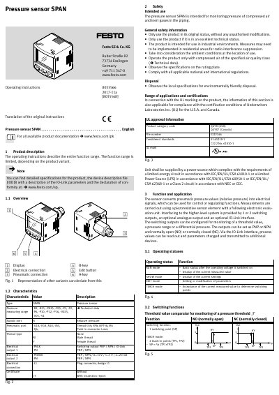
This document provides operating instructions for the Festo SPAN pressure sensor, detailing its function, installation, configuration, and operation. It includes technical specifications, safety instructions, application range, and user interface operations. The sensor converts pneumatic pressure into electrical signals for control or regulation, with configurable switching outputs and optional IO-Link interface. Installation and commissioning must be performed by qualified personnel, with attention to mounting position, condensate, and temperature.
| Pressure Measuring Range | -B2, -B11, -P025, -P05, -P1, -P2, -P6, -P10, -P12, -P16, -V025, -V05, -V1 |
|---|---|
| Pneumatic Port | -G18, -R18, N18, -M5, -Q4, Thread Gx , Rx , NPTx, M5 Push-in connector 4 mm |
| Electrical Output 2 | PNVBA-PN PNP / NPN / 0…10 V / 1…5 V / 4…20 mAPNP / NPN |
| Electrical Connection | -L1 Plug connector, design L1 |
The pressure measuring range includes -B2, -B11, -P025, -P05, -P1, -P2, -P6, -P10, -P12, -P16, -V025, -V05, -V1.
The maximum permissible line length is 30 m (20 m for IO-Link).