
Guidelines for mounting heat sinks on Fairchild power semiconductor packages to achieve optimal thermal performance.
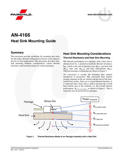
This application note explains how to mount heat sinks on Fairchild power semiconductor devices. It covers thermal resistance concepts, contact pressure, and the influence of mounting torque for a variety of package types such as TO‑220, TO‑247, and 7PM‑GA.
The document describes several mounting methods—screw, clip, rivet, and solder—along with recommended torque ranges, the role of thermal grease, washers, and insulating materials. It also provides tables of typical torque values and pressure‑loading calculations to help engineers select the proper mounting technique for reliable thermal management.
| Mounting torque (kgf·cm) – TO220 (typical) | 4 ~ 5 |
|---|---|
| Mounting torque (kgf·cm) – TO220 (maximum) | 7 |
| Mounting torque (kgf·cm) – TO3P | 8 ~ 10 |
| Mounting torque (kgf·cm) – 7PM‑GA | 18 ~ 20 |
| Thermal grease function | Reduces contact thermal resistance |
The typical torque is 4 to 5 kgf·cm, with a maximum of 7 kgf·cm.
Thermal grease fills the air gap between the package and heat sink, lowering contact thermal resistance.
Clip mounting is more stable and safe because it distributes uniform pressure over the mating surface.
A washer slightly increases thermal resistance by adding an extra contact surface.