
This manual provides installation, wiring, startup, and technical data for the Balluff BTL5 series Micropulse Linear Transducer with analog output.
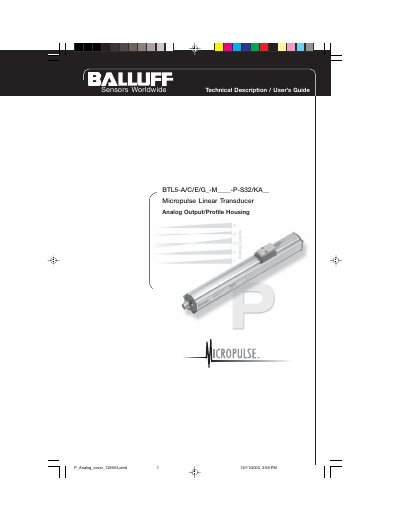
This document serves as a technical description and user's guide for the Balluff BTL5-A/C/E/G Micropulse Linear Transducer featuring an analog output and profile housing. It covers essential topics including safety advisories, system function, and available stroke lengths and magnet types.
| Supply Voltage | 24 Vdc ±20% or ±15 Vdc ±2% |
|---|---|
| Protection Rating | IP 67 |
| Output Signal | 0 to 10Vdc, -5 to +5Vdc, 0 to 20 mA, 4 to 20 mA, -10 to +10 Vdc |
| Standard Stroke Lengths | 148mm to 3606mm |
This guide is intended for specialized personnel who will perform the installation and setup of the system.
The recommended spacing is A = 80 mm for bracket spacing and B = 250 mm between individual brackets.
The maximum tightening torque for the M5 x 22 socket head cap screws is 2 Nm.