
This document describes the features and installation guide of AKS 4100 / AKS 4100U Liquid Level Sensor - Cable version.
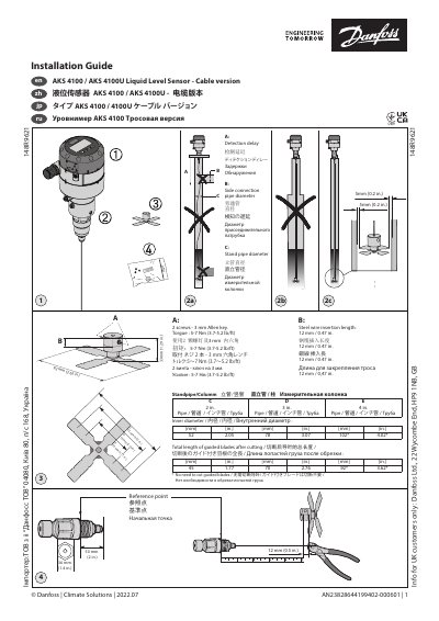
This document provides installation instructions for the Danfoss AKS 4100 and AKS 4100U liquid level sensors with a cable version. It details mechanical installation requirements, including pipe dimensions and torque specifications for securing the sensor.
The guide covers electrical connections for various configurations, such as linking the sensor to EKC 347 or PLC systems, and explains how to configure the device using the HMI Quick Setup menu to adjust units and output scaling.
| Torque for screws | 5-7 Nm (3.7-5.2 lb/ft) |
|---|---|
| Steel wire insertion length | 12 mm / 0.47 in. |
| Output signal | 4-20 mA |
| Power supply (PLC connection) | 14-30 V d.c. |
The torque should be set between 5-7 Nm (3.7-5.2 lb/ft).
It depends on the factory setting of the dielectric constant of the refrigerant.
These markers indicate a hardware problem where the Signal Converter hardware is defective.