
The AL8863 is a step-down DC-DC controller designed to drive LEDs with high output current. The device operates at an input supply voltage from 4.5V to 60V. Series connection of the LEDs provides identical LED currents resulting in uniform brightness and eliminating the need for ballast resistors. The switching frequency range of AL8863 is from 50kHz to 1MHz. The wide operating frequency range allows more flexibility on component selection, and also with operating up to 1MHz, it allows the use of smaller size external components, hence minimizing the PCB size and driver board.
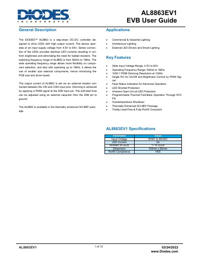
The Diodes AL8863EV1 EVB user guide describes an evaluation board for the AL8863 step-down DC-DC controller used to drive LEDs. The board accepts a 5 to 60 VDC input, is preset for 3A LED current, supports 1 to 16 LEDs, and measures 102mm x 60mm.
The guide includes connection instructions, schematic and PCB layout, bill of materials, quick start steps, functional waveforms, efficiency and LED current curves, PWM dimming data, CISPR 15 EMI results, and thermal test images.
| Input Voltage | 5VDC to 60VDC |
|---|---|
| LED Current | 3A |
| Number of LEDs | 1~16 LEDs |
| Dimension | 102mm x 60mm |
| RoHS Compliance | YES |
The power supply input is 5 to 60 VDC.
By default, the evaluation board is preset at 3A LED current by R1, R2, and R3.
Remove C15 and apply a PWM signal to the DIM pin; the recommended PWM frequency is 100 Hz to 20 kHz.
Add a low-pass filtered DC signal using R6 and C15 and drive the DIM pin between 0.3 V and 2.6 V.