
Instruction Stroke Length Controller
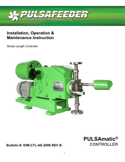
The Pulsafeeder PULSAmatic controller is an actuator that converts the reciprocating motion of a PULSA Series pump into rotary motion to turn the pump's stroke adjustment screw. It uses two brake housings, two one-way clutches and two helix nuts; energizing one brake rotates the adjustment screw in one direction, and energizing the other rotates it in the opposite direction. A feedback potentiometer and limit switches provide position feedback, and an override switch allows manual adjustment with a hand wheel.
This bulletin IOM-CTL-AE-2006 Rev B gives installation, operation and maintenance instructions. It covers equipment inspection, wiring and start-up, deadband and circuit board calibration, repairs such as limit switch adjustment and brake air gap, parts ordering, manual-to-PULSAmatic conversion, and troubleshooting.
| Input Signal: 1-5 mA DC | 1-5 mA DC at 2000 ohm impedance |
|---|---|
| Input Signal: 4-20 mA DC | 4-20 mA DC at 470 ohm impedance |
| Input Signal: 10-50 mA DC | 10-50 mA DC at 180 ohm impedance |
| Input Signal: 0-10 V DC | 0-10 V DC at greater than 270,000 ohm impedance |
| Slide Wire Input | Remote 1000-ohm manual control potentiometer, user-supplied |
| Current Output: 0-10 mA DC | 500 ohm impedance maximum |
| Current Output: 4-20 mA DC | 250 ohm impedance maximum |
The 4-20 mA DC input has an impedance of 470 ohms.
The 0-10 mA DC current output has a maximum impedance of 500 ohms.
It disconnects the brakes from the circuit board so the hand wheel can be used for manual adjustment.
Reverse acting inverts the signal response; for example, a 4-20 mA signal gives full stroke at 4 mA and zero at 20 mA.