
This manual introduces the specifications, usage methods and other information of the EA75A220 automatic voltage regulator.
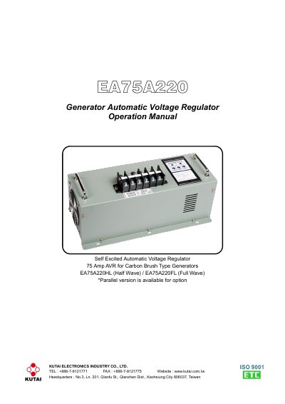
This manual provides instructions for installing, adjusting, and troubleshooting the EA75A220 Automatic Voltage Regulator, designed for carbon brush type generators. It covers specifications, wiring connections, frequency selection, field flashing procedures, and troubleshooting common issues. The regulator is available in half-wave and full-wave versions and includes safety warnings for proper installation and operation.
The manual includes detailed adjustment steps for voltage and stability, under frequency protection settings, and field flashing to resolve voltage build-up problems. It also outlines safety precautions and installation guidelines to prevent damage or injury.
| Input Voltage | 170 – 265 Vac, 1 phase 2 wire |
|---|---|
| Input Frequency | 50 / 60 Hz |
| Operating Temperature | -40 to +60 ˚C |
| Storage Temperature | -40 to +85 ˚C |
| Continuous Current | 75A |
| Dimensions (HL) | 120.0 (L) x 120.0 (W) x 38.0 (H) mm |
| Dimensions (FL) | 420.0 (L) x 191.0 (W) x 180.0 (H) mm |
| Weight (HL) | 6.6 kgs |
| Build Up Voltage | 5 Vac |
The EA75A220 is available in two versions: EA75A220HL (Half Wave) and EA75A220FL (Full Wave).
Adjust the STAB (POT) anti-clockwise until the voltage becomes unstable, then slightly adjust it clockwise (about 1/5 turn) until the voltage is stable yet very close to becoming unstable.
Check if the field polarity is reversed (swap F+ and F-) or if the residual voltage is less than 5 Vac. If so, perform field flashing by connecting a resistor (3–5 ohms for full wave, 5–10 ohms for half wave) for 3 seconds, or install the Kutai EB500 automatic flash module.
Turn the U/F POT fully clockwise, adjust the VOLT POT to nominal level, and reduce engine speed to the knee point. Then turn the U/F POT counter-clockwise until the voltage starts to decrease (U/F lamp illuminates), and re-adjust engine speed to rated speed.