
This is a maintenance manual for JVC AX-311BK product, which includes safety precautions, specifications, front panel, operation, removal procedures, adjustment procedures, block diagram, internal IC block diagram, connection diagram, schematic diagrams, insertion printed circuit boards, insertion parts list, etc.
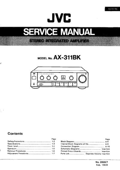
This service manual covers safety precautions, technical specifications, front‑panel functions, connection diagrams, and step‑by‑step removal and adjustment procedures for the JVC AX‑311BK stereo amplifier. It also includes parts lists, accessory information, and packing details to assist qualified service personnel.
The document is organized into sections such as Safety Precautions, Block Diagram, Specifications, Front Panel description, Connection Diagram, Operation, Removal Procedures, Adjustment Procedures, Parts List, Accessories List, and Packing Materials, providing a comprehensive reference for maintenance and repair tasks.
| Output power (4 Ω) | 80 W per channel at 1 kHz |
|---|---|
| Output power (8 Ω) | 60 W per channel at 1 kHz |
| Total harmonic distortion | 0.007 % (55 W, 8 Ω) |
| Frequency response | 5 Hz – 80 kHz (+0.3 dB, 8 Ω) |
| Dimensions | 435 mm (W) × 127 mm (H) × 310 mm (D) |
| Weight | 7.2 kg (15.9 lb) |
The leakage current must not exceed 0.5 mA AC (r.m.s.).
Remove the six screws and lift the rear section while pulling the cover backward.