
the DC1717A uses the LTC®4417 to arbitrate between three input supply rails, selecting the highest priority, valid supply to power the load.
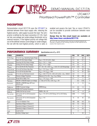
This document describes the DC1717A demonstration circuit, which uses the LTC4417 to select the highest priority valid input rail to power a load. The circuit supports three input rails (V1-V3) with configurable overvoltage and undervoltage thresholds. It includes design details, modification options, and transient behavior equations for component selection.
The LTC4417 controls external MOSFETs to connect the valid rail to the load, with logic and LEDs for status indication. The board requires a 6V–24V auxiliary input (AVI) for operation, which powers pull-up resistors for VALID pins. Modifications can eliminate AVI by removing jumpers and resistors, though LEDs will remain unpowered.
| Load Current | 2 A |
|---|---|
| Auxiliary Voltage Input | 6 to 24 V |
| Gate Driver Slew Rate | 4 to 22 V/µs |
| Break-Before-Make Time | 0.7 to 3 µs |
The maximum load current is 2 A.
Remove jumpers JP2 and JP3 and resistor R19 to eliminate the auxiliary input requirement.
The gate driver slew rate ranges from 4 to 22 V/µs.