
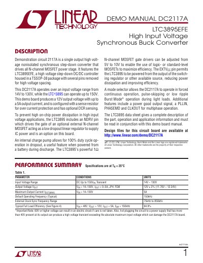
This datasheet introduces the LTC3895EFE high input voltage synchronous buck converter demonstration circuit DC2117A, which is a single output high voltage non-isolated synchronous step-down converter that drives all N-channel MOSFET power stages. It features the LTC3895EFE, a high voltage step-down DC/DC controller housed in a TSSOP-38 package with several pins removed for high voltage spacing. This DC2117A operates over an input voltage range from 14V to 130V, while the LTC®3895 can operate up to 150V. This demo board produces a 12V output voltage with up to a 5A output current, and is configured with a sense resistor for over current protection and has optional DCR sensing. To prevent high on-chip power dissipation in high input voltage applications, the LTC3895 includes an NDRV pin which drives the gate of an optional external N-channel MOSFET acting as a low dropout linear regulator to supply IC power and is an option on this board. An internal charge pump allows for 100% duty cycle operation in dropout, a useful feature when powered from a battery during discharge. The LTC3895's powerful 1Ω L, LT, LTC, LTM, Linear Technology, Burst Mode and the Linear logo are registered trademarks of Linear Technology Corporation. All other trademarks are the property of their respective owners.
The DC2117A is a demonstration circuit designed to evaluate the performance of the LTC3895EFE, a high voltage step-down DC/DC controller. This single output nonisolated synchronous step-down converter drives an N-channel MOSFET power stage and operates with an input voltage range of 14V to 130V, producing a 12V output with up to 5A of current. The board features an optional DCR sensing configuration for the inductor and includes an internal charge pump for 100% duty cycle operation in dropout conditions.
| Input Voltage Range | 14V to 130V |
|---|---|
| Maximum Output Current | 5A |
| Output Voltage | 12V ± 2% |
| Default Operating Frequency | 150kHz |
| External Clock Sync Frequency Range | 75kHz to 850kHz |
| Typical Full Load Efficiency | 94.9% |
The DC2117A operates over an input voltage range from 14V to 130V.
Yes, setting JP5 to the ON position activates 100% duty cycle operation in dropout.