
LT6110 Cable/Wire Drop Compensator
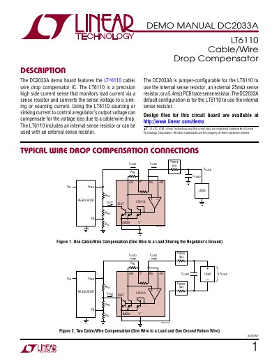
This document provides setup and application instructions for the DC2033A demo board, which uses the LT6110 IC to compensate for voltage drop in cables and wires. It includes jumper configurations for internal, external, or PCB trace sense resistors, and explains how to connect the board to a regulator for testing. The manual also covers design equations and application circuits for various load current scenarios.
The board is jumper-configurable for different sense resistor options and includes pads for feedback resistors and compensation capacitors. It is designed for use with a regulator demo board and supports testing with internal, external, or PCB trace sense resistors, with detailed equations for calculating output voltage and current compensation.
| Supply Range | 2 to 50 V |
|---|---|
| Amplifier Input Offset Voltage | 100 to 300 µV |
| IOUT Current Error (Iin = 10pA) | 0.6 to 1.6 % |
| IOUT Voltage Range | 0.4 V to Vv |
| Supply Current | 16 to 30 µA |
The DC2033A can be configured using jumpers for internal, external, or PCB trace sense resistors. The default configuration uses the internal 20mΩ sense resistor.
The external 25mΩ sense resistor supports up to 6A at 70°C or 5A at 90°C.
Remove the feedback resistors from the regulator board and connect the regulator’s feedback pin (FB or Vper) to the DC2033A Vrs (E9). Also connect the Voy and GND of the regulator board to the REGULATOR (E1) and to the GND (E3) of the DC2033A respectively.