
This file is a user manual for DC512A product, which introduces the usage method and precautions.
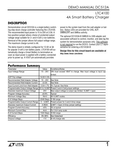
This document provides instructions for using the DC512A, a demonstration circuit for a single battery switching step-down charge controller. It includes setup procedures, jumper configurations for 3- and 4-cell Li-ion batteries, and operational details such as input voltage and current limits. The manual also describes optional software and hardware for monitoring and control.
The DC512A is designed to charge smart batteries with a maximum charge current of 4A. It features programmable output voltage and current ranges, status LEDs, and a VOUT pin for powering system loads. Safety features include a thermistor that may suspend charging if the board gets too warm.
| Input Voltage Range | 15 – 25V |
|---|---|
| Max Input Voltage | 25V |
| Max Input Current | 3.5A |
| Programmable Output Voltage Range | 6V to VLIMIT |
| Maximum Output Current | 4.092A |
| Efficiency | 85–96% |
The recommended input power is 15 to 20V at 3.5A.
Use the two-position jumper to select the output voltage range suitable for 3- or 4-cell Li-ion batteries.
The onboard NTC thermistor may trip and momentarily suspend the charge process, indicated by the fault LED turning on.