
This document is a quick start guide for LTC2485
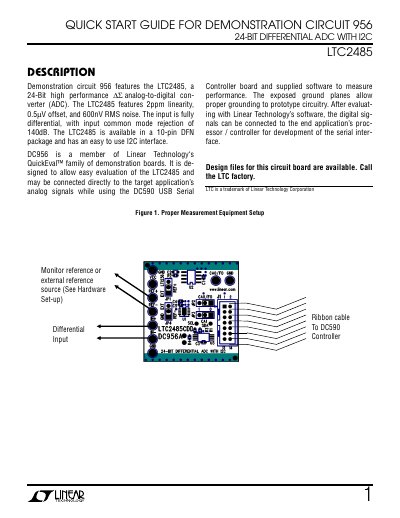
This guide explains how to set up and use the Demonstration Circuit 956 to evaluate the LTC2485 ADC. It includes hardware connections, software setup, and basic experiments to test input noise, common mode rejection, and normal mode rejection. The board connects to a DC590 USB Serial Controller for data acquisition and control.
The guide provides step-by-step instructions for connecting the board, running evaluation software, and performing experiments to verify the ADC’s performance characteristics such as 600nV RMS noise and 140dB common mode rejection.
| Resolution | 24-Bit |
|---|---|
| Linearity | 2ppm |
| Offset | 0.5mV |
| Noise | 600nV RMS |
| Common Mode Rejection | 140dB |
| Interface | I2C |
| Package | 10-pin DFN |
The resolution is 24 bits.
The input common mode rejection is 140dB.
Connect using the supplied 14-conductor ribbon cable.
Use the evaluation software supplied with DC590 or downloaded from http://www.linear.com/software.