
This document is a quick start guide to LTC2954-2, introducing the features and characteristics of this product
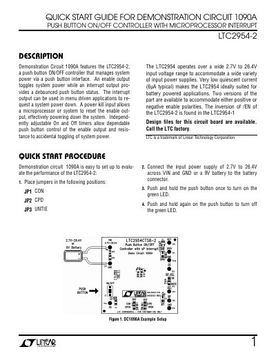
This quick start guide covers Demonstration Circuit 1090A (DC1090A), which features the LTC2954-2 push button ON/OFF controller. The controller manages system power through a push button interface: an enable output toggles system power while an interrupt output provides a debounced push button status. A power kill input lets a microprocessor or system reset the enable output to power down the system. Independently adjustable on and off timers provide push button control of the enable output and resistance to accidental toggling, and the part operates over a 2.7V to 26.4V input range with 6uA typical quiescent current. Two versions are available for positive or negative enable polarities, with the inversion of /EN of the LTC2954-2 found in the LTC2954-1.
The guide gives the setup procedure with jumper positions, input supply connection and push button operation, then explains the operating principles: the /PB pin, the /EN pin driving a P-channel MOSFET, the /KILL blanking timer, the power down delay, jumper-selected timers JP1 and JP2, the LEDs D1 and D2, and the optional RC networks for reverse polarity protection and push button filtering. A typical performance summary table and turn on/off waveform figures are included.
| Input Voltage (VIN) | 2.7V to 26.4V |
|---|---|
| Quiescent Current | 6 uA typical |
| /PB Turn On Time | 32ms (JP1 open); 32 + 212ms (JP1 on CAP) |
| /PB Turn Power Down Time | 32ms (JP2 open); 32 + 3014ms (JP2 on CAP) |
| On timer capacitor (ONT) | 0.033uF |
| Power down timer capacitor (CPD) | 0.47uF |
| LDO pull-up voltage (U2) | 2.6V |
Connect an input power supply of 2.7V to 26.4V across VIN and GND, or a 9V battery to the battery connector.
Push and hold the push button once to turn on the green LED, then push and hold again to turn it off.
JP1 selects the turn on timer, while JP2 is used to adjust the power down /PB duration.
The red LED D1 shows the state of the /INT pin.
Two versions of the part accommodate either positive or negative enable polarities; the inversion of /EN of the LTC2954-2 is found in the LTC2954-1.