
This document introduces the LT3744 high current synchronous inverting buck-boost LED driver application circuit. The circuit can connect the anodes of three LEDs together in both the step-down configuration and the inverting buck-boost configuration for better heat sinking.
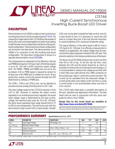
This document is a demonstration manual for the DC1930A circuit board, which utilizes the LT3744 High Current Synchronous Inverting Buck-Boost LED Driver. The board is designed to test the inverting buck-boost configuration, allowing for high current output up to 12A with a maximum output voltage of 6.05V. It features three independent outputs controlled by PWM pins and supports analog dimming via CTRL pins.
| Input Supply Voltage | 7V to 30V (Board Operating) |
|---|---|
| Maximum Output Voltage | 6.05V |
| Output Current | 12A |
| Efficiency | 89.3% |
It is designed for customers to test the inverting buck-boost configuration of the LT3744.
The recommended operating input range is 7V to 30V at room temperature.
The board has three independent outputs, each capable of up to 12A.