
This document is the installation manual of AF1 series measurement transducers. It introduces the installation methods and usage methods.
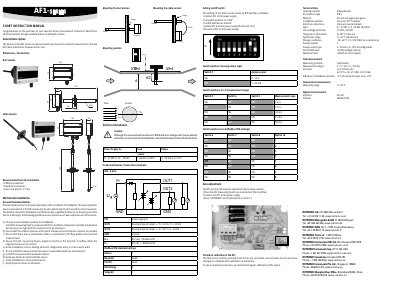
The document serves as a short instruction manual for the ROTRONIC AF1 series measurement transducers, designed for airspeed measurements. It covers general descriptions, dimensions, connection types (duct and cable versions), and mounting procedures to ensure precise airflow detection in various environments.
Key operational features include manual zero adjustment via an AUTOZERO button and reconfigurable settings using DIP switches. The guide details electrical installation precautions, terminal allocation, power supply requirements, and communication protocols such as Modbus RTU over RS-485.
| Measuring principle | Calorimetric |
|---|---|
| Measurement ranges | 2 / 5 / 10 / 15 / 20 m/s |
| Precision | ±3.0 % full-scale at 23 °C ±3 K, 45 %RH, 1013 mbar |
| Power supply | 8...35 VDC or 12...30 VAC |
| IP protection type | IP65 |
| Interface protocol | Modbus RTU |
Place the measuring head in an environment free of airflow, connect it to power, and press "AUTOZERO" while holding it down for at least 5 seconds.
The manual recommends a Phillips screwdriver, a standard screwdriver, and an open-end wrench of 27 mm.
Yes, the device allows switching between 0...10 V and 4...20 mA outputs using DIP switch position 2.