
This is a user manual which introduces the features and installation methods of the PF1 differential pressure transmitter.
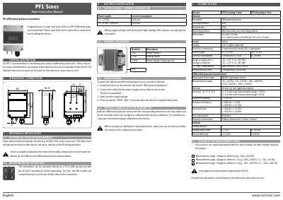
This document is a short instruction manual for the Rotronic PF1 series differential pressure transmitters. It provides essential information regarding mechanical mounting on DIN rails or walls, electrical supply requirements (DC/AC), terminal assignments, and commissioning procedures including zero adjustment.
The guide details technical data for two versions: the PF135 analog 3-wire and the PF120 analog 2-wire. It specifies operating conditions such as temperature ranges, accuracy levels based on measurement range, output types (0...10 V or 4...20 mA), and physical dimensions.
| Power Supply (DC) | 12...32 VDC |
|---|---|
| Power Supply (AC) | 12..24 VAC 50/60 Hz |
| Current Consumption (DC) | <300 mA |
| Housing Material | ABS |
| IP Protection | IP65 |
| Dimensions (Excluding conduit) | 84 x 66 x 36 mm |
| Weight | 100 g |
| Display Type | LCD, 4 digits (optional) |
| Measurement Principle | MEMS diaphragm sensor |
Press the "ZERO" button 15 seconds after the device is supplied with power.
Regular calibration is recommended for maximum accuracy, though the sensor and electronics are very stable.
Tubes with an internal diameter of 4 mm, such as AC6001/XX, can be connected.