
This is the official icom VHF AIR BAND TRANSCEIVER iA210 iA210E installation guide, which introduces the installation method, precautions and other contents of the product.
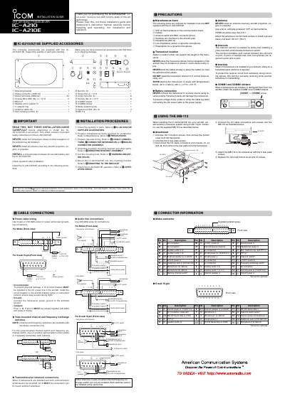
This document provides installation instructions for the Icom IC-A210/A210E VHF Air Band Transceiver. It details the supplied accessories, safety precautions regarding aircraft navigation and antenna placement, and step-by-step procedures for assembly and mounting.
The guide covers electrical connections using either Molex or D-sub 15-pin connectors, including power wiring with circuit breakers, audio line connections for microphones and headphones, and intercom switch configurations. It also explains the use of the MB-113 adapter for aircraft utilizing different connection systems.
| Power Circuit Breaker Rating | 10 A |
|---|---|
| VSWR Requirement | Less than 2.5:1 |
| Ground Plane Size | At least 18 in² (120 cm²) |
The transceiver is supplied with a mounting bracket, Molex connector and terminals, screws, washers, C-shaped rings, antenna cable clips, self-crimping nuts, COMM stickers, and an MB-113 adapter.
A 10 A circuit breaker must be installed in the DC power line to prevent physical damage and ensure easy access during flight.
No, either an intercom or a yoke-mounted channel/frequency exchange switch can only be installed; both cannot be used at the same time.