
The ADI Chinese version data sheet is a translation of the English version data sheet, which introduces the features and characteristics of ADI's four-channel protector ADG5462F, including user-defined secondary power supply overvoltage level, overvoltage protection, and power-off protection.
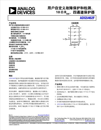
The ADG5462F is a four-channel protector designed to protect sensitive devices from overvoltage faults in the signal path. It features user-defined positive (POSFV) and negative (NEGFV) fault voltage thresholds, allowing customization of protection levels based on system requirements.
Key characteristics include low on-resistance (10 Ω typical), flatness across a wide analog signal range, and latch-up immunity via trench isolation. The device supports both dual-supply operation (±5 V to ±22 V) and single-supply operation (8 V to 44 V). It provides digital fault indication via the DR pin when an overvoltage condition is detected. This manual is written in Chinese.
| Threshold Voltage (VT) | 0.7 V typical |
|---|---|
| Supply Voltage Range (Dual) | ±5 V to ±22 V |
| ESD Rating (HBM) | 4 kV |
The device supports dual-supply operation from ±5 V to ±22 V and single-supply operation from 8 V to 44 V.
The device provides digital output indication via the DR pin when an overvoltage condition is detected.