
The STOD13AS is a 250mA dual DC-DC converter for powering AMOLED displays. It integrates a step-up and an inverting DC-DC converter making it particularly suitable for battery operated products, in which the major concern is overall system efficiency. It works in pulse skipping mode during low load conditions and PWM-MODE at 1.5MHz frequency for medium/high load conditions. The high frequency allows the value and size of external components to be reduced. The Enable pin can be used for shutdown mode. The low quiescent current enables STOD13AS to save battery power in standby mode.
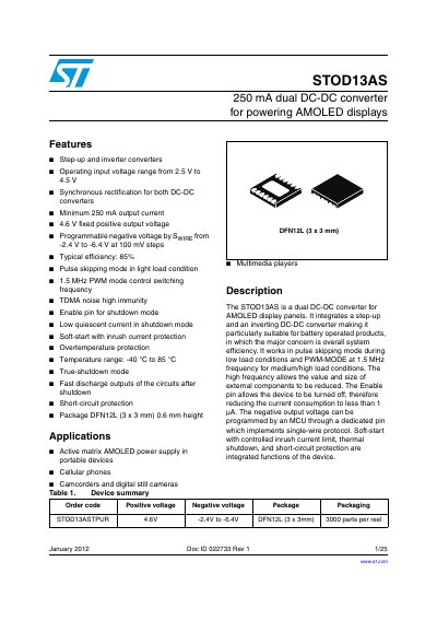
The STOD13AS is a dual DC-DC converter designed for powering AMOLED display panels in portable devices like cellular phones and cameras. It integrates a step-up converter and an inverting converter to generate a fixed 4.6 V positive output and a programmable negative output ranging from -2.4 V to -6.4 V. The device features synchronous rectification, pulse skipping mode for light loads, and a 1.5 MHz switching frequency to minimize external component size.
| Operating input voltage range | 2.5 V to 4.5 V |
|---|---|
| Positive output voltage | 4.6 V fixed |
| Negative output voltage range | -2.4 V to -6.4 V |
| Minimum output current | 250 mA |
| Switching frequency | 1.5 MHz |
| Typical efficiency | 85% |
| Temperature range | -40 °C to 85 °C |
| Package type | DFN12L (3 x 3 mm) |
The device operates in PWM mode with a 1.5 MHz switching frequency for medium and high load conditions.
The negative output voltage is programmable via the SWIRE pin, allowing settings from -2.4 V to -6.4 V in 100 mV steps.
The converter automatically switches to pulse skipping mode to improve efficiency under light load conditions.