
The UC1824 family of PWM control ICs is optimized for high frequency switched mode power supply applications. Particular care was given to minimizing propagation delays through the comparators and logic circuitry while maximizing bandwidth and slew rate of the error amplifier. This controller is designed for use in either current- mode or voltage mode systems with the capability for input voltage feed-forward. Protection circuitry includes a current limit comparator with a 1V threshold, a TTL compatible shutdown port, and a soft start pin which will double as a maximum duty cycle clamp. The logic is fully latched to provide jitter free operation and prohibit multiple pulses at an output. An under-voltage lockout section with 800mV of hysteresis assures low start up current. During under-voltage lockout, the outputs are high impedance. These devices feature totem pole outputs designed to source and sink high peak currents from capacitive loads, such as the gate of a power MOSFET. The on state is designed as a high level.
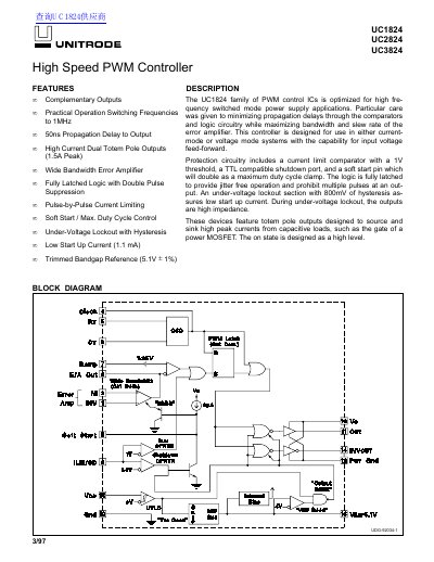
This document details the UC1824 family of PWM control ICs, which are optimized for high-frequency switched mode power supply applications. The controllers support both current-mode and voltage-mode systems with input voltage feed-forward capabilities. Key features include fully latched logic, double pulse suppression, and high-current dual totem pole outputs capable of driving power MOSFET gates.
The datasheet provides comprehensive electrical characteristics for the UC1824, UC2824, and UC3824 variants, covering reference sections, oscillators, error amplifiers, and protection circuits. It also includes application notes on PCB layout considerations, oscillator circuit designs, and test fixture information.
| Oscillator Initial Accuracy | 400 kHz |
|---|---|
| Unity Gain Bandwidth | 35.5 MHz |
| Output Sink Current | 12.5 mA |
| Supply Start Up Current | 1.1 mA |
| Under-Voltage Lockout Start Threshold | 9.2 V |
| Power Dissipation | 1 W |
The initial accuracy of the oscillator at 25°C is typically 400 kHz.
The unity gain bandwidth of the error amplifier is 35.5 MHz.