
STGD7NB60H-1 is a N-channel 7A - 600V IPAK PowerMESH IGBT with outstanding perfomances designed by STMicroelectronics based on a patented strip layout. The suffix ”H” identifies a family optimized to achieve very low switching times for high frequency applications (<120kHz). It is used in high frequency motor controls, SMPS and PFC in both hard switch and resonant topologies.
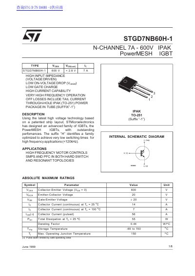
This document is a datasheet for the STGD7NB60H-1, an N-channel 7A 600V PowerMESH™ IGBT. The device features a high input impedance and low on-voltage drop, designed for high-frequency motor controls and SMPS applications. It is housed in a through-hole IPAK (TO-251) power package with a suffix "-1" indicating a tube packaging option.
The datasheet provides absolute maximum ratings, electrical characteristics, and dynamic parameters such as switching times and losses. It includes thermal data, safe operating area graphs, and mechanical dimensions for the TO-251 package. The document specifies that the device is optimized for very low switching times suitable for frequencies below 120kHz.
| Collector Current (continuous) at Tc = 25 °C | 14 A |
|---|---|
| Collector Current (continuous) at Tc = 100 °C | 7 A |
| Total Dissipation at Tc = 25 °C | 55 W |
| Package Type | IPAK (TO-251) |
| Max. Operating Junction Temperature | 150 °C |
It is designed for high frequency motor controls and SMPS and PFC in both hard switch and resonant topologies.
The maximum collector current at 25 °C is 14 A.
The typical collector-emitter saturation voltage is 2.8 V.