
This article describes the method of designing a low-cost power supply using VIPer12/22A-E in a buck configuration. The power supply is suitable for many applications and can provide power for 12V and 16V outputs. The design features the lowest possible component count, integrated thermal overload protection, approximately 200mW of no-load consumption, and efficiency measured between 70% to 80%.
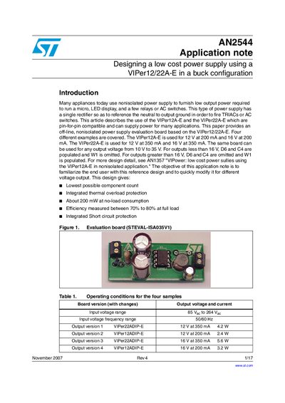
The document details an off-line, nonisolated power supply evaluation board based on the VIPer12A-E and VIPer22A-E controllers. It covers four specific design examples providing outputs of 12V at 200mA/350mA and 16V at 200mA/350mA, utilizing a single rectifier to reference neutral to output ground for firing TRIACs or AC switches.
The guide provides circuit operation details including input line rectification, start circuits, inductor selection formulas, and board layout recommendations. It includes schematics for different voltage/current configurations and discusses design trade-offs regarding inductor values and thermal performance.
The VIPer12A-E supplies 12 V at 200 mA and 16 V at 200 mA, while the VIPer22A-E supplies 12 V at 350 mA and 16 V at 350 mA.
The board operates with an input voltage range of 85 V ac to 264 Vac.
The actual measurements of the PC board are 55 mm by 23 mm.