
ST2S06 is a dual synchronous step-down DC-DC converter optimized for powering low-voltage digital cores in ODD applications and, generally, used to replace the high current linear solution when the power dissipation may cause a high heating of the application environment. It provides up to 0.5 A over an input voltage range of 2.5 V to 5.5 V. A high switching frequency (1.5 MHz) allows the use of tiny surface-mount components. A resistor divider to set the output voltage value, an inductor and two capacitors are required for every channel. In addition, a low output ripple is guaranteed by the current mode PWM topology and by the use of low ESR surface-mount ceramic capacitors. The device is thermal protected and current limited to prevent damage due to accidental short-circuit. The family is available in the QFN12L (4x4 mm) package.
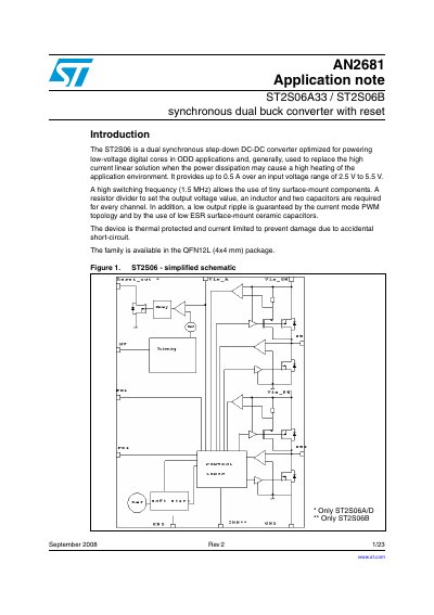
The document introduces the ST2S06 family of dual adjustable current mode PWM synchronous step-down DC/DC converters. These devices are optimized for powering low-voltage digital cores in ODD applications, offering up to 0.5 A output over an input voltage range of 2.5 V to 5.5 V with a high switching frequency of typically 1.5 MHz.
| Output Current | 0.5 A |
|---|---|
| Input Voltage Range | 2.5 V to 5.5 V |
| Switching Frequency | 1.5 MHz |
| Package Type | QFN12L (4x4 mm) |
There are three versions: ST2S06A and ST2S06D with a reset function, and ST2S06B with an inhibit function.
Every channel requires a resistor divider to set the output voltage, an inductor, and two capacitors.