
This document presents a solution for designing a transition mode PFC preregulator using the L6562A. The L6562A is the latest proposal from STMicroelectronics for low and middle power applications such as lamp ballasts, high-end adapters, flat TVs and monitors, and PC power supplies. It is also suitable for emerging markets that may require low-cost power factor correction. Based on a well-established architecture, the L6562A offers excellent performance that considerably enlarges its field of application.
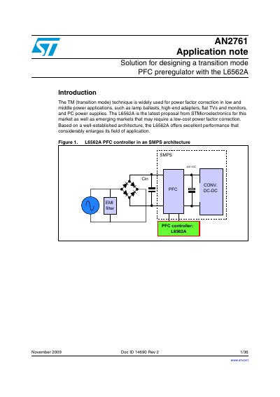
This document describes the Transition Mode (TM) technique for power factor correction (PFC) in low and middle power applications. It focuses on the design of a PFC preregulator using the L6562A controller from STMicroelectronics, which is designed for low-cost power factor correction solutions.
The guide covers the operation of the TM PFC with a boost topology, detailing how the L6562A shapes input current to be sinusoidal and in phase with the input voltage. It includes sections on designing the power section components, such as the bridge rectifier, input and output capacitors, boost inductor, MOSFET, and diode. Additionally, it provides a design example using an Excel spreadsheet and presents test results from an EVL6562A-TM-80W demonstration board.
The DC output voltage must be higher than the maximum expected line peak, which is typically 400 VDC.
The MOSFET turns off when the voltage on the current sense pin equals the sinusoidal reference from the multiplier block.
Transition mode operation is suggested for lower power applications, typically below 200 W.