
A2525EL/M and A2535EL/M are integrated high-side power switches, optimized for self-powered and bus-powered Universal Serial Bus (USB) applications
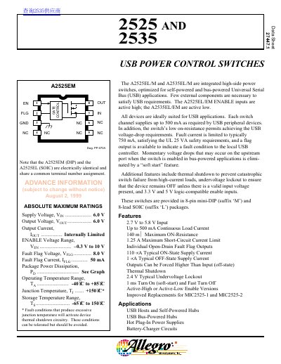
This document describes the A2525 and A2535 USB power control switches, which are integrated high-side power switches optimized for self-powered and bus-powered Universal Serial Bus (USB) applications. The devices are available in 8-pin mini-DIP and 8-lead SOIC packages and feature active high or active low enable inputs.
| Operating Voltage Range | 2.7 V to 5.8 V |
|---|---|
| Maximum Load Current | 500 mA |
| Package Types | 8-pin mini-DIP and 8-lead SOIC |
The switch channel supplies up to 500 mA as required by USB peripheral devices.
An open-drain fault flag output is asserted to indicate the fault condition to the local USB controller.
An internal thermal-sense circuit shuts off the power switch when the junction temperature rises to approximately 165°C.