
This document introduces 5V and 12V power line protection based on STEF05 and STEF12 electronic fuses. These electronic fuses are designed to monitor the output current and input voltage and protect the electronic circuitry from overcurrent and overvoltage. They have programmable turn-on time to control the inrush current during startup and hot-swaps. When an overload condition occurs, the electronic fuse limits the output current to a predefined safe value. If the abnormal overload condition persists, it goes into an open state, disconnecting the load from the power supply. Both devices are equipped with a thermal protection circuit.
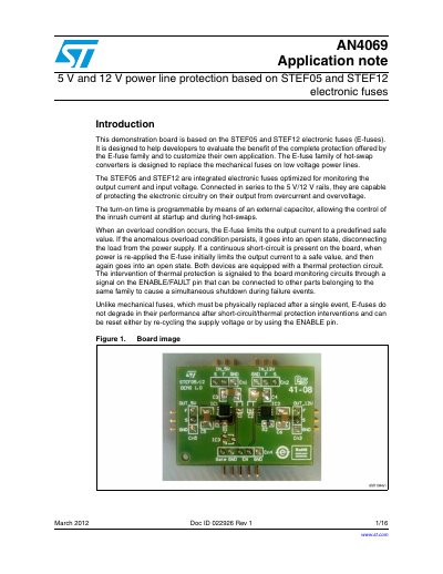
This document presents an application note (AN4069) for a demonstration board designed to evaluate the STEF05 and STEF12 electronic fuses. These devices are integrated hot-swap converters intended to replace mechanical fuses on 5 V and 12 V power lines, providing protection against overcurrent, overvoltage, and thermal faults. The board allows developers to customize turn-on time and slew rate using external capacitors and to link the ENABLE/FAULT pins for simultaneous shutdown.
| Input voltages | 5 V and 12 V |
|---|---|
| Continuous current | 3.6 A typ. each |
| Short-circuit current limit (STEF05) | 2.9 A |
| Short-circuit current limit (STEF12) | 4.4 A |
The turn-on time is programmable by means of an external capacitor connected to the dV/dt pins.
The device can be reset by pulling the ENABLE/FAULT pin down to the off/reset region (Vey <0.8 V) or by re-cycling the power supply.
The suggested values for the dV/dt capacitors range from 10 pF to 1 nF.