
This application note describes a demo board able to drive a 54 W linear T5 fluorescent lamp. The ballast control is done by the L6585D that integrates PFC and half-bridge control circuits, the relevant drivers, and the circuitry able to manage all lamp operating phases (pre-heating, ignition and run mode). Protections against main failures (lamp disconnection, anti-capacitive mode, PFC over-voltage) are guaranteed and obtained with a minimum number of external components. Finally, the electronic solution allows better control of the filament current and lamp voltage during pre-heating with the unquestionable benefit of increasing the mean lamp life.
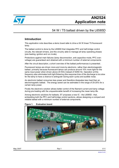
This document describes a demonstration board designed to drive a 54 W linear T5 fluorescent lamp. The ballast control is managed by the L6585D integrated circuit, which combines PFC and half-bridge control circuits with drivers to manage lamp operating phases including pre-heating, ignition, and run mode. The design ensures protections against main failures such as lamp disconnection and PFC over-voltage with a minimum number of external components.
The note details the application specifications, including input voltage ranges and lamp characteristics, and lists the schematic and part values. It further explains the board's performance regarding Power Factor (PF) and Total Harmonic Distortion (THD), and describes various protection mechanisms implemented in the circuit, such as PFC over-voltage, choke saturation, and lamp disconnection detection.
| Lamp Power | 54 W |
|---|---|
| PFC Output Voltage | 429 V |
| Minimum Switching Frequency | 34 KHz |
| PFC Over-voltage Limit | 468 V |
The ballast control is done by the L6585D that integrates PFC and half-bridge control circuits.
The circuit guarantees protections against lamp disconnection, anti-capacitive mode, and PFC over-voltage.