
This document describes the application of a constant current inverse buck LED driver using L6562A. It provides details on the main characteristics of L6562A and summarizes the relevant results obtained.
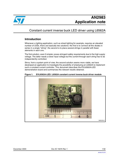
This document describes the EVL6562A-LED demonstration board, which implements a constant current inverse buck LED driver using the L6562A controller. The design is intended for lighting applications requiring an elevated number of LEDs, such as street lighting, and addresses safety requirements associated with high supply voltages.
The application note details the system configuration, circuit description, and measurements of the module. Key features include a 48V input voltage, digital dimming capability, open-/short-circuit protection, and the absence of electrolytic capacitors. The document provides electrical schematics, a bill of materials, and analysis of LED voltage and input voltage dependencies.
| Input voltage | 48 V (+/- 20%) |
|---|---|
| Output current (average) | 0.35 A |
| Output ripple current | < 140 mA (+/- 20%) |
| Controller | L6562A |
| Reference voltage | 1.08 V (nom.) |
It implements a constant current source for LED strings using an inverse buck topology.
The board's design takes into account an input voltage of 48 V with a tolerance of +/- 20%.
The load current is set by applying a voltage between 0 and 12 V to the C_Set pin.
Yes, the design includes open-/short-circuit protection.