
This document provides recommendations and measurements for EMI filters, as well as the features and characteristics of the products. It discusses the filtering and protection functions against radio frequency interference and electromagnetic interference, as well as the data transmission function.
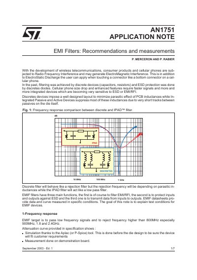
This document discusses the challenges of Radio Frequency Interference (RFI) and ElectroMagnetic Interference (EMI) in wireless telecommunications and cellular phones. It explains the limitations of discrete filtering devices compared to integrated passive and active devices (IPAD) and details the functions of EMI filters in filtering noise, protecting against ElectroStatic Discharge (ESD), and transmitting data.
The note provides specific guidance on test conditions and measurement techniques. It covers frequency response simulations and measurements, ESD and latch-up protection strategies including layout considerations, and crosstalk measurements for both digital and analog signals using specific test circuits and equipment.
The filter is designed to reject frequencies higher than 800MHz, specifically targeting 900MHz, 1.8GHz, and 2.4GHz.
The standard specifies a surge generator charged up to 8kV for contact discharge and 15kV for air discharge.
With a correct layout, the maximum output voltage remains close to 8.4V when subjected to a 15kV surge.