
The L6208 is a highly integrated, mixed-signal power IC that allows the user to easily design a complete motor control system for two-phase bipolar stepper motors.
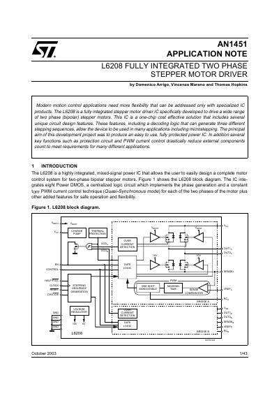
The document is an application note for the STMicroelectronics L6208, a fully integrated mixed-signal power IC designed to drive two-phase (bipolar) stepper motors. It details the internal architecture, including eight Power DMOS transistors, phase generation logic, and PWM current control techniques.
The text provides specific guidance on designing applications with the L6208, covering critical parameters such as current ratings (up to 5.6A peak total), voltage operating ranges (8V to 52V supply), and the selection of bulk capacitors. It also addresses layout considerations to minimize noise from high dv/dt nodes and explains various protection features like Over Current Detection (OCD) and Under Voltage Lock Out (UVLO).
| Maximum Output Current (per pin) | 2.8A r.m.s. |
|---|---|
| Maximum Output Current (peak) | 5.6A |
| Supply Voltage Range | 8V to 52V |
| Under Voltage Lock Out Threshold | 6V |
| DMOS Drain-Source Breakdown Voltage | 60V |
The operating range for the supply voltage (Vs) is from 8V to 52V.
Yes, the device has a built-in Over Current Detection (OCD) that provides protection against short circuits.
The bulk capacitor, placed between Vs and GND pins, is charged and discharged during IC operation to handle AC current capability.