
This application note introduces how to design an inductive fluorescent lamp ballast using the ST7LITE0 microcontroller.
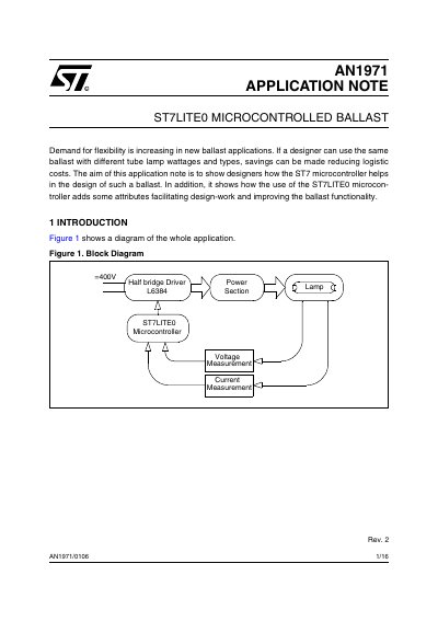
This document details an application using the ST7LITEO microcontroller to design a flexible fluorescent ballast capable of driving different tube lamp wattages. The system utilizes a voltage-fed series resonant half-bridge inverter driven by an L6384 high voltage driver. The microcontroller handles all control logic, including power-on initialization, preheating, ignition, and stabilization phases, while measuring lamp current and voltage via integrated ADC peripherals.
The application note outlines the specific operating states of the ballast, including the Init, Preheat, Ignition, Lamp Stabilization, Run, and Stop states. It explains how the ST7LITEO's Autoreload Timer and Lite Timer facilitate PWM generation and time-based event handling, respectively. The document also provides circuit diagrams for peak and average current sensing, as well as peak and DC voltage sensing, to ensure complete monitoring of the ballast circuitry.
| Flash Program Memory | 1.5kB |
|---|---|
| RAM | 128 bytes |
| EEPROM | 128 bytes |
| Integrated Oscillator Accuracy | 1% |
| Maximum Clock Frequency | 8MHz |
| ADC Resolution | 8-bit |
| ADC Input Range 1 | 0 to 5V |
| ADC Input Range 2 | 0 to 250mV |
| ADC Amplifier Gain | 8 |
| PWM Frequency Range | 2kHz up to 4MHz |
| Incremental Period Change | 125ns |
| Lite Timer Interrupt | every 1ms |
| Supply Voltage | 400V DC |
| Driver Component | L6384 |
The design uses the ST7LITEO microcontroller to handle control and measurement.
Frequency is controlled by writing to the Reload Value Register of the Autoreload Timer.
Duty cycle is selected by writing to the Compare Value Register of the Autoreload Timer.
The software switches to HALT mode to turn off the half bridge driver and minimize energy consumption.