
AN3410 is an LED driver application note released by ST, which introduces a LED driver circuit design that meets the requirements of the US market. This circuit uses ST's L6564 power factor controller in a non-traditional circuit to regulate the input power to a step-down switching regulator. The circuit also compensates for variations in LED voltage drop, to maintain the average output current in a tight band over a wide range of line voltage and LED characteristics. While the input current waveform is not perfectly sinusoidal, power factor and harmonic content are well within the requirements for the US commercial market. The form factor was designed to fit into the PAR38 envelope - the driver and LEDs can be used to replace 65 W incandescent floodlamps.
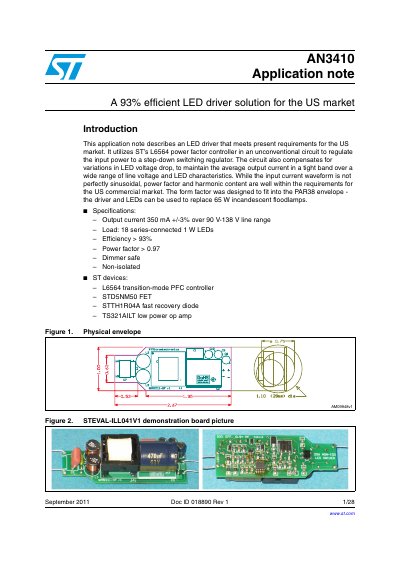
The document details an LED driver circuit designed to meet US commercial market requirements with over 93% efficiency and a power factor greater than 0.97. The design utilizes ST's L6564 power factor controller in an unconventional configuration to regulate input power for a step-down switching regulator driving 18 series-connected LEDs.
| Output current | 350 mA +/-3% |
|---|---|
| Load configuration | 18 series-connected 1 W LEDs |
| Efficiency | > 93% |
| Power factor | > 0.97 |
The output current is maintained over a line range of 90 V to 138 V.
No, the circuit is designed as a non-isolated solution.