
The TD351 is an advanced IGBT driver with integrated control and protection functions. It is suitable for driving 1200V IGBT modules. It features a minimum output peak sink current of 1A and source current of 0.75A over the full temperature range (-20°C to 125°C), active Miller clamp function, and optional 2-step turn-off sequence.
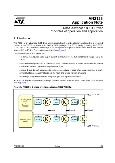
This document describes the TD351, an advanced IGBT driver with integrated control and protection functions designed for 1200 V IGBTs. It is a simplified version of the TD350, available in SO8 or DIP8 packages, and is part of the TD35x family adapted for Econopak-like modules.
The note details the device's main features, including active Miller clamp functionality to reduce induced turn-on risks, an optional 2-step turn-off sequence to protect against over-voltage, and input stage compatibility with both optocouplers and pulse transformers. It provides application examples for three-phase inverters and explains how to configure the input and output stages.
| Output current sink (min) | 1 A |
|---|---|
| Output current source (min) | 0.75 A |
| Operating temperature range | -20°C to 125°C |
| Input signal threshold (turn-on) | < 0.8 V |
| Input signal threshold (turn-off) | > 4.2 V |
| Recommended gate resistor | >= 15Ω |
The gate resistor should not be lower than about 15Ω.
Yes, but the active Miller clamp feature allows negative supply voltage to be avoided in most cases.
The input signal must be lower than 0.8 V for a minimum of 220 ns.